

How Things Work
This is where we explain how a few interesting bits of aviation kit work. The choice of subject is pretty arbitrary. |
|
The Constant Speed Propeller
The Constant Speed Propeller revolutionised engine management when it made its debut in the 1930s.
It provided a way of keeping the engine revolutions constant - with the benefit of less pilot effort.
|
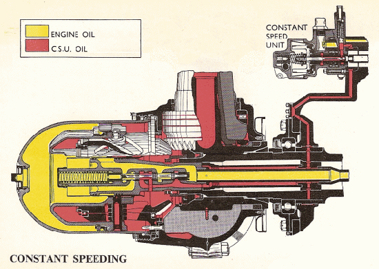 |
| The Constant Speed Propeller hub shown above in section is a de Havilland Hydromatic propeller, which has been
used by many aircraft from the 1930s onwards and is still in use today. As you can see, the hub is actually a cylinder
with a piston that can move forwards and backwards. The piston carries lugs that are engaged in helical slots in a
cylinder, and there is one cylinder for each propeller blade. If the piston moves forwards or backwards, the lug rotates
the cylinder, thus causing the gear teeth mounted at its rear end to turn the gear teeth mounted on the root of the of
the propeller blade. If the piston moves forwards, the blades are twisted to coarse pitch, and if the piston moves
backwards, the blades are twisted to fine pitch. The piston is made to move forwards or backwards, depending on the
difference in the pressure of the oil behind and in front of the piston; and this is controlled by the CSU.
Propellers used on multi-engine aircraft were usually of the feathering type. Feathering consisted of twisting the blades so that they turned edge-on to the airflow, thus offering less drag should the engine stop. Since the engine could no longer provide pressurised oil to make the pitch mechanism work, feathering was done by use of a separate oil pump. |
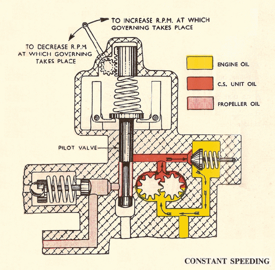 |
| The CSU controls the flow of oil to the propeller hub. This sketch shows the situation where the engine is turning at a constant speed, and as a result the CSU is keeping the oil pressure the same both in front and behind the hub piston. This situation will alter either with a change in the engine running conditions (such as the pilot changing the power setting or the engine reacting to a change in ambient conditions such as the air temperature), or with the pilot actually wanting to change the rpm. In this constant speed condition, a simple meshed-gear oil-pump pumps engine oil continuously, but the oil only moves round a closed circuit through a relief valve. At the top of the unit, a rotating-weight governor, driven from the engine, keeps the Pilot Valve in a closed condition. As long as the rotating-weight governor is stable, oil flow will continue in closed-circuit. |
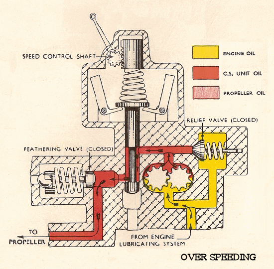 |
| Now let us look at a situation where either the pilot moves the rpm control to decrease the propeller revolutions, or the engine rpm increases for some reason. In the first case the pilot moves the control lever down and relieves pressure on the spring, which causes the Pilot Valve to lift. In the case of the engine increasing its speed the governor weights move apart, and this too will cause the Pilot Valve to lift. In both cases, the lifting of the Pilot Valve will cause the oil to be pumped away from its closed circuit and out towards the propeller hub. This increases the pressure on the oil behind the piston, and when this is moved forwards it causes the cylinder with the helical groove to rotate and turn the propeller blades to a coarser pitch. As the blades take 'bigger bites' of air, the engine is forced to slow down. As the engine slows down the governor weights come together again, allowing the Pilot Valve to lower and block off the flow of oil. The propellor speed is now stable at the new pitch setting. |
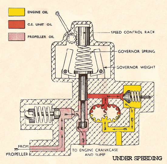 |
| Now let us look at a situation where either the pilot moves the rpm control to increase the propeller revolutions, or the engine rpm decreases for some reason. In the first case the pilot moves the control lever up and increases pressure on the spring, which causes the Pilot Valve to lower. In the case of the engine decreasing its speed the governor weights move together, and this too will cause the Pilot Valve to lower. In both cases, the lowering of the Pilot Valve will allow oil to flow back from the propeller hub and towards the engine oil circuit. The oil is pushed back to the CSU by the higher pressure of the engine oil pushing on the front of the piston. When the piston is pushed backwards under pressure of the engine oil it causes the cylinder with the helical groove to rotate and turn the propeller blades to a finer pitch. As the blades take 'smaller bites' of air, the engine is allowed to speed up. As the engine speed increases, the governor weights move apart again, allowing the Pilot Valve to raise and block off the flow of oil from the hub. Once again, the propellor speed will now stabilise at the new pitch setting. |
The Jet Engine
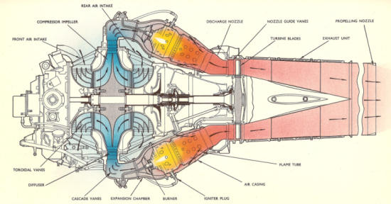 |
The Goblin Centrifugal Jet Engine |
| The first jet-engines operated by the RAF had centrifugal compressors. These featured a double-sided impeller
which would draw air in from intakes in front of and behind it and compress the air by flinging it outwards, at which
point it entered the ring of combustion chambers where it was mixed with fuel and ignited. The resulting hot,
pressurised gas would pass through a turbine, which would rotate and, being linked by a shaft to the compressor, would
provide power for the compression of the air. There was a limit to the compression that centrifugal compressors could
achieve and they were superceded within a few years by engines with axial flow compressors.
The Goblin engine, designed by de Havilland, delivered 3,000 lbs thrust and was used in the Gloster Meteor and the de Havilland Vampire, some examples of which still fly today. |
© Copyright 2007 CairdPublications.com | Site Map | Contact Us |