
RAF Armament Bits - Guns
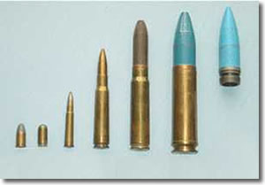 |
Aircraft Armament AmmunitionThe growing punch of aircraft armament since WWI. From the left: .455 Webley Pistol (Revolver) - WWI |
The RAF variant of the Typhoon (Eurofighter) will not carry the 27mm cannon because, in the words of a minister, 'the airframes will last longer' if cannon are not installed and used. Funny - the Mauser has been built with a special recoil system to minimise strain on the airframe; and the RAF has not seen too many Jaguars falling to bits over the last 30 years due being shaken apart by use of the cannon... Our revered government spokesmen need to get better scripts - how about simply 'kerching!'? Update! The MOD has now realised that deleting the cannon will now be more expensive than installing them. Suddenly the concern for the airframe has evaporated! Kerching!! |
|
Courtesy of the Fife Collection |
|
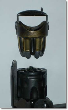
Prideaux Loader for Webley RevolverTo increase firepower, many servicemen armed with the Webley revolver, including RFC observers, would carry a number of Prideaux loaders. These would hold six rounds in sprung steel fingers and the revolver would be reloaded by positioning the loader on the empty cylinder, and with one swift (albeit sometimes muscular) push the rounds would be inserted into the cylinder. |
 |
| Courtesy of the Fife Collection | |
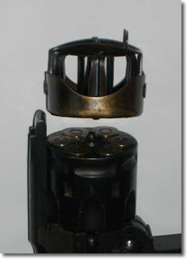
Prideaux Loader DischargedOnce the loader had done its work the revolver could be closed and would be ready again. Before machine guns were installed in RFC aircraft, rifles and pistols were used to try to down the opposition. The rate of fire of the revolver was higher than a rifle for those vital few seconds when the enemy aircraft might be close enough to stand a realistic chance of being hit. |
|
| Courtesy of the Fife Collection | |
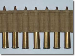
Vickers Machine Gun BeltWhen Vickers machine guns were first installed in WWI fighters (they actually called them Scouts for the first few years) they used the normal canvas ammunition belt. This required the careful insertion of rounds into the loops to ensure a snug fit, and on a damp day the belt would get wet and the gun would invariably jam. The belts were of a fixed length of 250 rounds. |
 |
| Courtesy of the Fife Collection | |
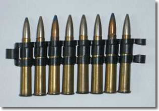 |
Browning Machine Gun BeltSo, belts made of disintegrating metal links were developed that allowed perfect positioning of rounds and which were not affected by damp. Also, the belts could in theory be any desired length. For example, the Lancaster rear gun turret had 2,500 rounds per gun - 1,900 in the ammunition tanks and 600 in the feed chutes. The example shown in the photograph is for the Browning .303 machine gun and shows how rounds of different types: ball, incendiary, explosive etc. were mixed in the belt. |
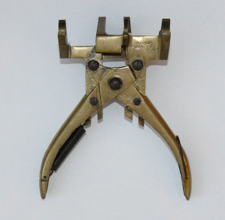
Make and Break ToolMost machine gun belts were made up by machines which could turn out belted ammunition at a respectable rate. However, when belts needed to be broken and linked up again a tool was provided to save the fingers from repetitive strain injury (although the term had not yet been invented). The Make and Break tool comprised a pair of articulated pliers with a set of claws on each side. On squeezing the handle, one set of claws would pull a cartridge and link together, while the other set of claws would pull them apart. |
 |
| Courtesy of the Fife Collection | |
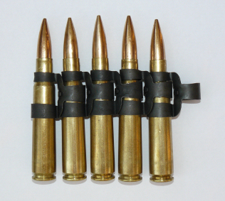 |
Fifty Calibre Machine Gun BeltThe Browning fifty calibre machine gun was a scaled up .300, and was used in a number of RAF warplanes. Where the weight of a .303 bullet was 174 grains, the weight of a fifty calibre bullet was about four times that and would defeat any airborne armour in use by the Luftwaffe. The rate of fire of most guns was about 13 per second, but a two-gun turret fifty calibre was still more effective than a four-gun .303. |
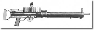
The Lewis GunFirst made in 1911, the Lewis Gun (designed by Col. Isaac Newton Lewis, US Army Retd.) was a very practical example of a light machine gun. It was adopted by the British in 1914 and was a natural choice for the air services. |
 |
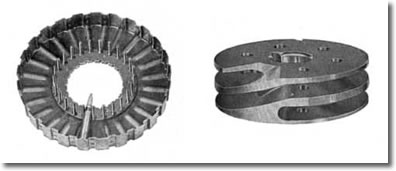 |
Lewis Gun MagazineThe ammunition for the Lewis Gun was stored in a circular 'pan' magazine on the top of the body, and the important parts of this are shown in an inverted position. Each cartridge was held at the shoulder by metal fingers and at the base by a recess in the edge of the pan body, and |
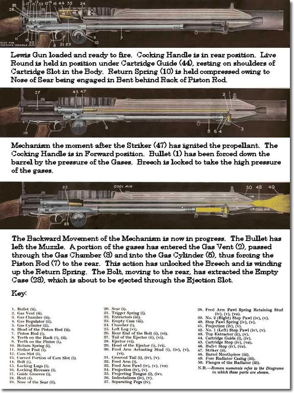
the forward part of the cartridge was inserted in a spiral ramp of aluminium which fitted in the centre of the pan. When firing took place, the aluminium ramp remained stationary with its exit point positioned over the gun breech while the pan body rotated around it, thus guiding each cartridge in turn down the spiral to the cartridge slot. Moving the mass of ammunition in this way was a significant load on the mechanism, and the rate of fire of the Lewis Gun was only 700 rounds per minute. The magazine shown above is the 47 round type. The 97 round type would have a deeper pan, and the spiral would be two cartridge layers higher - to hold the additional 50 cartridges. The Lewis Gun continued in RAF service until the 1930s, when it was replaced by the Vickers Gas Operated gun (very similar to the Lewis) and the Browning. How the Lewis Gun WorkedThe Lewis Gun was a gas operated machine gun, and the diagrams below show the sequence of movements of the mechanism as a shot is fired. Note that this example, for ground use, had a tubular sheath with cooling vanes around the barrel and gas cylinder, through which cooling air would be drawn as the muzzle blast sucked air in from the breech end. |
|
 |
|
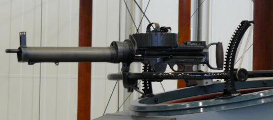
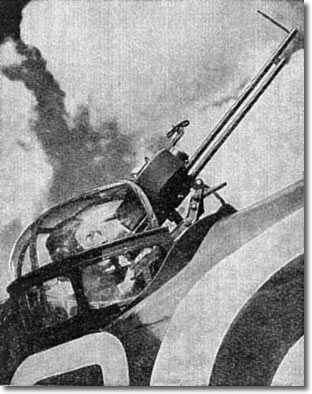
A Lewis Gun in a DH9This Lewis Gun is mounted in the rear cockpit of a WWI DH9 aircraft. The firing position can be altered for high elevation targets by moving the gun-carrier ring up the sprocketed support arc, and moved to port or starboard by sliding sideways on the ring. |
 |
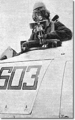 |
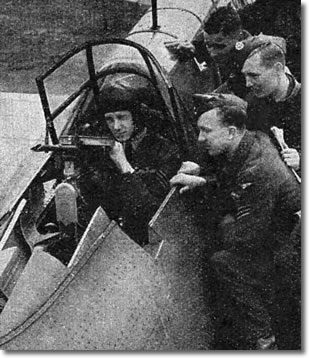
A Lewis Gunner of 603 SqnA gunner of the pre-war 603 "City of Edinburgh" Squadron encourages a papparazzo to retire behind the rope cordon with the rest of the onlookers. |
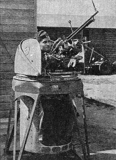
Powered Turret for a Lewis GunIn medium-sized aircraft it was practical to install powered turrets to enable the gunner to keep the gun steady and to track smoothly. Here is a Lewis Gun, stripped of any cooling jackets (the slipstream kept the barrel cool), in a mid-1930s powered turret. |
 |
The Vickers Gas Operated ("K") machine gunThe Vickers Gas Operated machine gun was similar in concept to the Lewis Gun but had a higher rate of fire - about 950 RPM. Much of the higher rate of fire was due to the introduction of a spring in the magazine pan which positively pushed the rounds of ammunition towards the cartridge slot. The magazines came in two sizes: 60 rounds and 100 rounds (illustrated). The VGO was also used on the ground - and it was a particular favourite of the men of the Long Range Desert Group of the 8th Army in North Africa who mounted them in pairs on their jeeps and lorries. |
 |
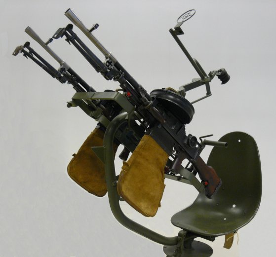
A Pair of BREN guns with Pan MagazinesA pair of BREN Guns with Pan Magazines are mounted on a simple frame for Airfield Defence.
|
 |
 |
VGO in a Fairey BattleIn smaller aircraft, such as this Battle, the gunner had to use a free mount. Note the slot in the fuselage just behind the gun position - for tidy stowage of the gun when the canopy was closed. |
The Lewis/VGO Camera Training GunHere is a gun-training camera for VGO gunners installed in the mid-upper turret of a Bristol Blenheim. Note the camera lens on the front of the magazine pan. |
 |
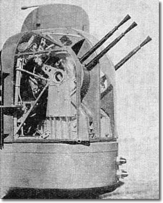 |
Rear Turret of a Whitley BomberSafety in numbers; the four .303 Colt Brownings installed in the rear turret of a Whitley bomber. |
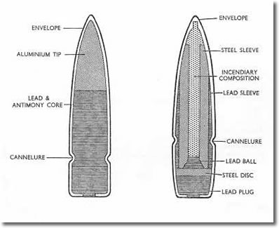
303 Incendiary BulletTo make the small .303 bullet more effective against an aircraft, various types of ammunition were introduced. This shows a comparison between the standard ball round (left) and the incendiary round (right). |
 |
 |
20mm High Explosive/Incendiary ShellA variety of ammunition for the Hispano 20mm cannon of the RAF was also developed. After a few years of use, the favoured types of shell were the Semi-Armour Piercing/Incendiary (SAP/I) and the High Exposive/ Incendiary (HE/I). Here is a sectional view of the HE/I shell. The idea was that after the high explosive had gone bang, the incendiary stuff would be spread liberally around the target. |
Hispano 20mm cannon Front ViewThe Hispano cannon was the mainstay of RAF fighter armament from the middle of the war onwards. Initially it was fitted with a 60 round magazine, which was about twice the diameter of the Belt Feed Mechanism shown in the photograph. The magazines were initially unreliable, until a stronger driving spring was fitted. |
Hispano 20mm cannon Rear ViewThe Hispano cannon was eventually fitted with the Belt Feed Mechanism (BFM) illustrated, which pulled linked 20mm ammunition from the ammo tank and into the breech of the cannon. The BFM contained a drive spring which was initially tensioned by hand, but as each shot was fired the recoil of the cannon caused the BFM to rewind the spring to compensate - thus allowing the use of any length of linked ammunition. |
 |
The Rocket Projectile (RP)The Rocket Projectile was developed to give ground attack aircraft a weapon with the same accuracy and punch as a field gun. RP was introduced in 1943 but remained secret until mid-1944. |
 |
However, the Germans knew about RP during that entire period - they were being shot at with them. RP were fired from underwing rails, until after a few years it was realised that the aircraft's forward speed made launch accuracy quite dependable and simple clips, or saddles, were all that was needed. The 60 pound HE head (shown) had a hollow-charge and could penetrate 12 inches of armour. The 25 pound armour-piercing round was used against submarine hulls as it made a small hole that was usually too inaccessable for the crew to repair, and which made sinking inevitable. The overall weight of the missile (with 60 lb head) was 90 lbs. |
||
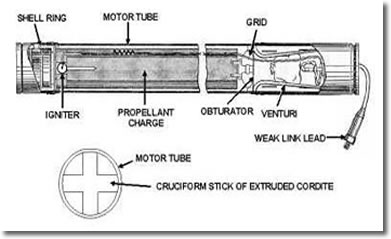 |
Schematic of Rocket ProjectileIn simple terms, the RP was a steel tube with an explosive projectile at one end and stabilising fins at the other. The Mark I motor used a hollow tube of Cordite weighing 12.5 pounds as its propellant, which burned fast and gave a high velocity. |
|
|
However, this was not safe for all deployments and so the Mark II motor used an 11.5 lb stick of Cordite of cruciform section doped with potassium cryolite, which was safer and made the exhaust less luminous. The terminal velocity of Mark II RP was slightly under sixteen hundred feet per second. |
||
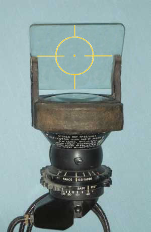 |
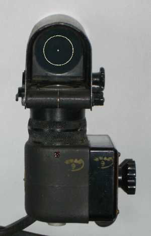
Reflector Gunsight MkIIThe Reflector Gunsight MkII was the mainstay of the RAF fighter from 1941 until the gyro gunsights began to enter service in 1944. The sprocket wheels could be set to a desired range and wingspan (Base) and the pilot would then frame the target aircraft between the horizontal lines in the gunsight image. (This shot has a simulated aiming image.) |
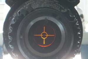
The Reflected Aiming PatternHere is a slightly unusual way of seeing the reflected aiming pattern - from the lamp housing at the bottom of the gunsight body, with sunlight shining down from the top. The wingtips of the target aircraft were to just touch the ends of the horizontal lines within the circle to get the range just right. |
 |
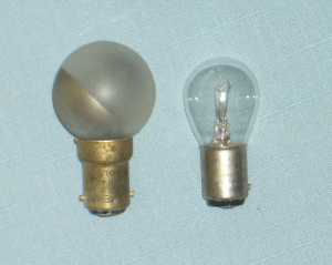 |
Reflector Gunsight BulbsThe Reflector Gunsight used a frosted, half-silvered bulb which lit up the aiming pattern at the bottom of the body of the sight. The bulbs were either 12 volt or 24 volt, depending on the aircraft (e.g. Spitfires were 12 volt, Typhoons were 24 volt).
|
Gunsight MarkIII Gunner's ViewThe Gunsight MkIII was a smaller reflector gunsight for use in gun turrets, such as those fitted to the aircraft of Bomber Command. The brightness of the sighting image (simulated in this shot) could be adjusted by use of the knob on the right hand side of the sight. There was also a sun-visor which could be moved to cope with a bright sky (shown up in this shot). |
 |
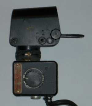 |
Gunsight MarkIII Side ViewHere is a shot of the right hand side of the sight showing the dimmer knob and also the knob on the sight shroud which was used to swivel the sun-visor down. The sun visor is shown in the down position. |
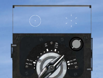 |
Gyro Gunsight MkIID Pilot's ViewBy early 1944, the Ferranti Gyro Gunsight MkIID was in production, and this would automatically compensate for the movement of the aiming aircraft. (We cannot find a quality front shot of the MkIID - this is an artist's impression.) The introduction of the MkIID brought about an immediate improvement in the rate at which enemy aircraft were shot down.
|
|
|
Note that the wingspan dial is not marked out in feet but only as a series of ten foot divisions, and the wingspan of well-known enemy aircraft types is marked in on the dial. Note also that the sight was issued before the Me262 was encountered, and this had a wing-span of 40 feet - where the span knob is pointing to in this image. The pilot would set the wingspan of the target aircraft on the sight and then use a twist-grip on the throttle lever to open and close the aiming pattern, which was a circular pattern of six diamonds. When the diamonds touched the wing tips of the target aircraft the range was
perfect for firing; and the gyro mechanism would have moved the aiming image to ensure that any deflection had been allowed for. The fixed aiming pattern on the left was provided for gun harmonisation and in case the gyro aiming pattern failed for any reason.
|
||
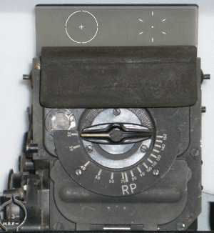
Gyro Gunsight Mk 4EThe RAF gyro gunsight most used post war, before head-up displays got clever and started using high-luminosity CRTs, was the GGSMk4E, which was fitted to many post-war fighters (apart from night-fighters, which continued to use the GMII). The need for a protective rubber buffer had brought about a redesign which resulted in the Mk4E having its span dial inverted. Also, the lever that raised and lowered the tinted filter glass was moved to the left hand side of the sight and the mechanism improved so that the filter glass would lie flush against the sight top.
|
 |
 |
Gyro Gunsight Mk 4E Right SideHere is a shot of the right side of the Mk4E sight, showing the equipment plate. |
GGS Mk4E Sun visor leverHere is a shot of the left hand side of the sight, showing the lever that moves the sun-visor up and down. It is in the up position in this shot. |
 |
 |
GGS4E Sun visor downIn this shot, the sun-visor is shown in the down position, the lever having been moved to the low position. The filter glass now lies flush with the body. |
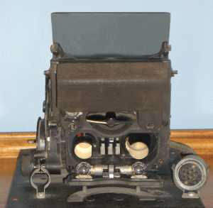
GGS4E Bulb HousingsLike the GMII, the GGS4E needed bulbs to light up the aiming pattern. Here, the front of the sight has been pulled down to show the position of the two bulbs that light up the fixed aiming image (left bulb) and the gyro-stabilised aiming image (right bulb).
|
 |
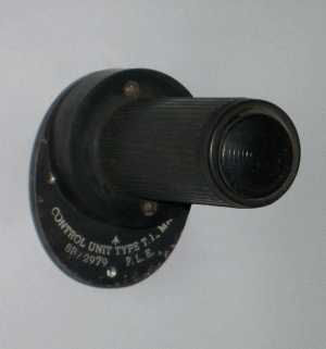 |
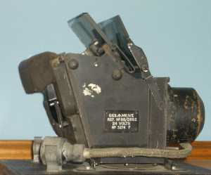
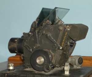
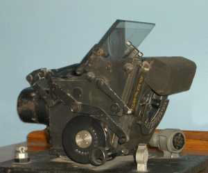
Throttle/Gyro Gunsight Control Unit Type T.1. Mk I Ref: 8B/2979 F.L.E.The throttle of a fighter equipped with the gyro gunsight had a twist-grip to adjust the range setting of the sighting image and a thumb-button to release bombs or RP.
|
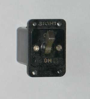
Gunsight switchA simple single-throw switch to turn a gunsight on. This may have been used in a number of applications, such as to switch on a single function sight such as the MkIII, but it has also been seen mounted next to a GGSIID as a master switch - other controls dimmed the sighting images. |
 |
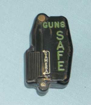 |
Post-war Gun ButtonPost war, the RAF wanted a gun and camera operating button that could be operated with complete safety. Since many aircraft control columns were either spade grip or two-handed yoke, a general purpose button was introduced. This incorporated a flap which exposed the camera button but kept the gun button safely covered. |
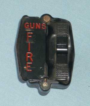
Post-war Gun Button OpenWhen the flap covering the gun button was flipped over to the left by the thumb, the gun button was exposed. Like the gun buttons of the latter part of the war, the gun button could be pressed at the top for one set of guns, the bottom for another set of guns (WWII aircraft often had a mixed armament of machine guns and cannon) and the centre if both sets were to be fired. Firing the guns automatically depressed the camera button as well. |
 |
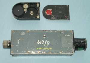 |
G45 Gun CameraThe G45 gun camera was used throughout WWII and post-war. The G45 would start filming when either a gun camera button was pressed or the aircraft guns were fired. The 16mm film was contained in small, die-cast tombstone-shaped magazines that could be changed over very quickly and which were opened easily by sliding the side off. The camera was powered by the aircraft's electrical supply and had separate circuits to cock and release the shutter, thus giving a crisp timing to each frame taken. |
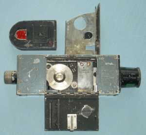
G45 OpenThe G45 could be installed in an aircraft either upright or on its side, since the magazine could be inserted either by opening the swinging flap at the top of the camera or by opening the hinged flap at the side. The lens housing contained heating elements to keep the lens clear in cold air; either during winter or when flying at altitude. |
 |
© Copyright 2007 CairdPublications.com | Site Map | Contact Us |