
RAF Reconnaissance Bits
Here are some images that mark the progress in aerial reconnaissance; and the countermeasures that were developed. |
|
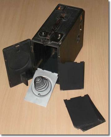
A Falling Plate CameraEarly air reconnaissance relied on binoculars and the ability to accurately mark up a map. Before specialised cameras became available, the 'Detective' or falling plate camera was favoured for its speed of use over the target area. The "Midg" camera could take twelve cut-film plates, stacked upright on rails behind the lens, and pushed forwards by the coiled spring. By moving the lever on top of the camera body the exposed plate would fall flat on the camera floor and the stack of plates would move forwards, to bring the next plate into the focal plane. A dozen well-framed shots could be taken in under a minute, even while wearing gloves. |
 |
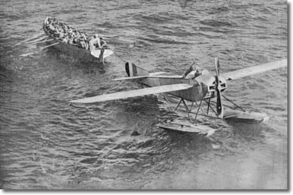 |
Seaplane recoveryA seaplane is towed back to its parent warship by matelot power after a reconnaissance flight over Turkish lines in the Dardanelles in 1915. The Turks were good shots and such flights usually resulted in a peppering of bullet holes in the fabric. |
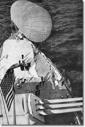
A USN Spotter BalloonA spotter balloon is prepared for flight from a US warship. In 1917 and 1918 the US Navy carried out many convoy escort duties and the towed spotter balloon was an effective weapon in the war against the U-boat. The term "dirigible", often heard in regard to US lighter-than-air craft, refers to a powered airship; from the French "can be directed". |
 |
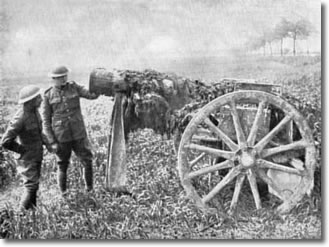 |
A Decoy Field GunOnce the effectiveness of aerial reconnaissance became known, decoys and camouflage became highly important. Here a decoy field gun is given a final inspection. |
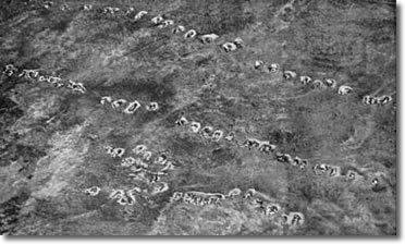
Advancing troops dig inAdvancing troops dig in during a temporary halt. This photograph was taken by a friendly aircraft, but the same shot taken by an enemy reconnaissance machine could have brought down artillery fire soon afterwards. |
 |
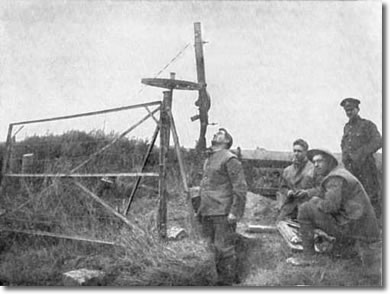 |
Countermeasures against low-fliersLow-flying spotters had to be discouraged; or dealt with more severely. Here a group of gunners rig up an ingenious anti-aircraft mounting for their Lewis gun. The infantry usually used the 47 round magazine on their Lewis guns as the 97 round magazine made the gun too top-heavy. |
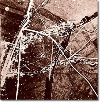
The Hindenburg LineEvery picture tells a story. Looking closely at this reconnaissance photo of part of the Hindenburg Line it is possible to see the firing bays, trenches, and where roads have been diverted around shell craters |
 |
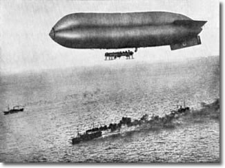 |
Convoy ProtectionAn air-to-air photograph of an airship on convoy protection duty. Far out at sea, reconnaissance from the air was only practical with towed balloons; as seen earlier on this page. In coastal waters, the airship could be used to spot for any signs of submarines lurking ahead of the convoy. |
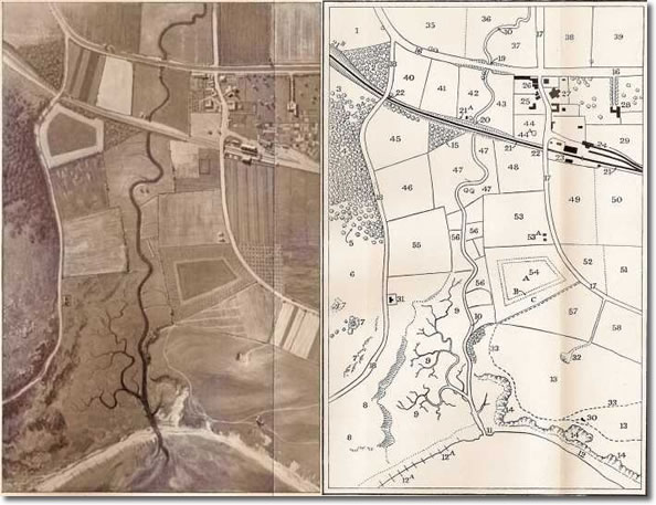
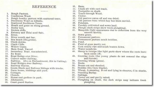
Taking good reconnaissance photographs was only the start; good interpretation of the photographs was also vital. WWI and after saw great strides in the interpretation of photographs. Below we see a sample photograph with a training index for the major features. This shows the degree to which interpretation could go; and how small clues could be vital to understanding what was going on. |
 |
 |
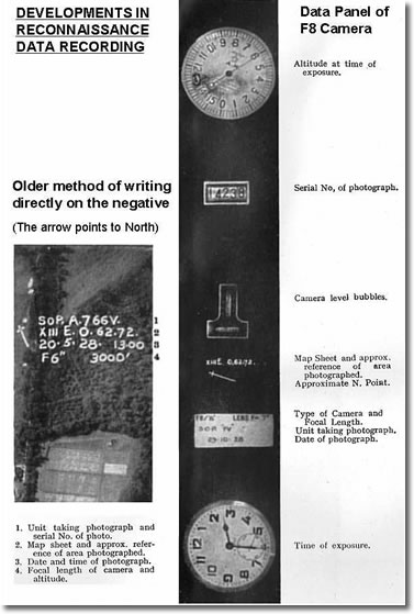
By the late 1920s, the older cameras were giving way to newer ones that automatically recorded the vital data relating to a photograph. Below we see a comparison between the older method of recording data on a photograph after the sortie, and the newer method of capturing that data within the camera and reproducing it on the edge of the final print. |
 |
Aerial reconnaissance mostly used three techniques; simple vertical photographs, which might overlap slightly to provide a mosaic of the terrain; oblique photographs, which were taken downwards and sideways so as to obtain an image without having to overfly the terrain; and stereoscopic series, where two photographs taken from differing overhead positions could be fused to provide a three-dimensional image. |
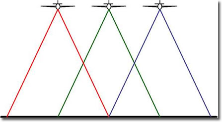 |
To obtain stereoscopic images, one or more aircraft would fly over the terrain on parallel tracks designed to overlap those either side by 50%. This would result in all of the terrain being photographed twice, but from different overhead positions. When two prints of the same piece of terrain were viewed simultaneously through stereo viewing equipment, the vertical features of the terrain would appear. Later RAF practice used a 60% overlap to ensure full coverage. |
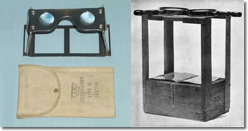 |
Above are shown two types of stereoscope. On the left is the well-engineered Type D that analysts could carry around, and on the right is an improvised stereoscope that could be knocked up in the field. Note the ingenious use of a slot cut in the middle of the box which allows the inner edges of the pairs of photographs to be diverted downwards, and thus not overlap. |
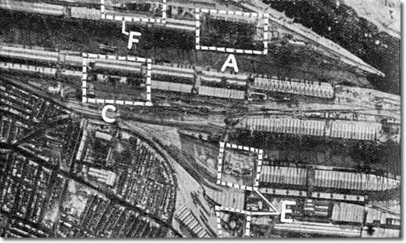 |
After a bombing raid, reconnaissance was used to verify damage. This photograh was taken of Bremen after a bombing raid and the analyst has marked in the damage. A is a warehouse, about 600 feet long; C is another warehouse of similar size; E shows damage to a power station and its coal store; and F ia a shed close to a petrol refinery. |
© Copyright 2007 CairdPublications.com | Site Map | Contact Us |